ZHC926-1KW/ZHC926-10KW Switcher Controller
1. Overview
The ZHC926 main/standby switch controller is a special device specially designed for broadcast and television transmitters to control the manual or automatic switching of the 1+1 main/standby transmitter system. It has automatic switching mode and manual switching mode.
In automatic switching mode, the switcher automatically detects the working status of the host: when the output power of the main transmitter is lower than the preset main transmitter power switching threshold (hereinafter referred to as "switching threshold"), the switch will control the coaxial switch And the main and backup transmitter power supply, automatically switch to the backup transmitter to work in order to achieve uninterrupted broadcast.
In manual switching mode, the panel switch can be used to manually operate, select the host or standby machine to work, and it automatically completes the switching control of the coaxial switch and the power supply of the main and standby transmitters.
Features:
l The switching threshold is calibrated by the user;
l No need for transmitter communication protocol support;
l LCD real-time display of the working status of the host and standby;
l Real-time reading of the coaxial switch contacts to ensure the safety of transmitter switching;
l Maintain various states before power failure;
l Remote monitoring of the switch can be realized through the remote interface;
l Using high-speed MCU processor control, stable and reliable performance;
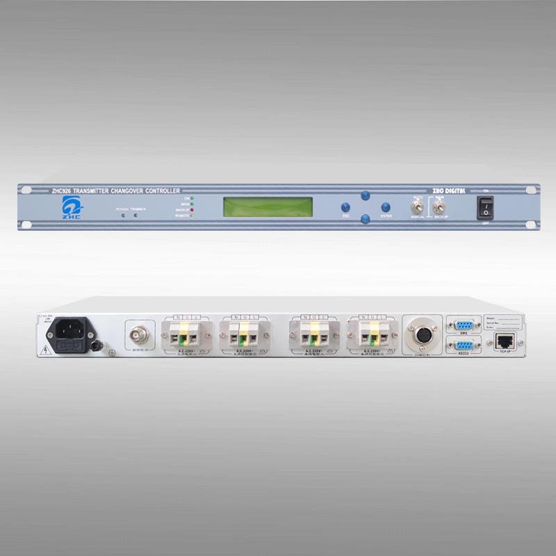
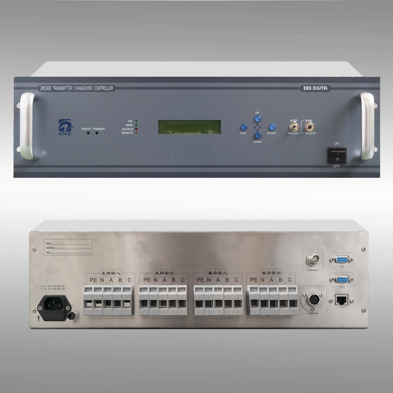
l Two power levels: 1KW and below (1U), 10KW and below (3U)
2. Technical Details
2.1 Electrical Specifications
Transmitter Power |
ZHC926-1KW |
0~1KW |
ZHC926-10KW |
1KW~10KW |
Main transmitter RF detection output range |
-5~+10dBm |
Maximum output current (for coaxial switch) |
AC 220V output 3A |
DC 5V/12V output 1A |
Switching time |
1~256 seconds user setting |
Equipment power |
AC220V/50Hz |
Device power consumption |
20W |
Communication support |
RS232 |
SMS modem |
TCP/IP |
CAN |
2.2 Physical Specifications
RF input detection interface |
BNC |
RS232 interface |
DB9 |
SMS modem interface |
DB9 |
CAN interface |
DB9 |
Ethernet interface |
RJ45 |
Chassis standard |
19 inch |
Chassis size |
1KW: 1U(440mm×44mm×300mm) |
10KW: 3U(440mm×132mm×500mm) |
Operating environment temperature |
—15~+50℃ |
Relative humidity |
<95% |
3. Working Principle
As shown in Figure 3-1, the ZHC926 transmitter switching controller is mainly composed of a detection control unit, a human-machine interface, a communication unit and related control relays.
The detection control unit reads the in-position contacts of the coaxial switch in real time to ensure that the main and standby transmitters and the coaxial switch work in a normal state.
In automatic mode, the switch detection control unit automatically detects the output power of the main transmitter, and controls the main and standby transmitter power supplies and the corresponding relays of the coaxial switch to achieve the switching function; in manual mode, the above is achieved by detecting the [selection switch] Function.
The man-machine interface, on the one hand, transmits the state of the buttons and [selection switch] to the detection control unit, on the other hand, it displays the various working states of the switch in real time through the indicator light and LCD.
The communication unit receives and parses the external commands through the protocol and transmits them to the detection control unit, and at the same time feeds back the device status to the remote device, thereby realizing remote monitoring.
The switcher uses a holding relay to control the power supply of the main and standby transmitters, which can maintain the normal operation of the main and standby transmitters even when the switch is abnormally powered off.