Digital FM tunnel broadcast coverage system and emergency broadcast

1. Introduction
In recent years, a large number of urban tunnels, highway tunnels, and railway (including subway) tunnels have been built in various places, effectively improving the transportation capacity.
At present, the coverage of mobile phone signals has been adopted as the standard configuration in the tunnel design stage, but the coverage of FM broadcast signals is generally not required, which causes the broadcast signal to be interrupted immediately after the vehicle enters the tunnel, causing inconvenience to the crew.
Listening to the radio is a common hobby of drivers, and many drivers use this method to learn about road conditions or relieve driving fatigue. Especially when a vehicle enters a long tunnel, if there is no broadcast signal, many drivers will feel bored, fearful, and may even cause a traffic accident.
At the same time, when traffic accidents, traffic jams, or even fires occur in the tunnel, the tunnel management personnel cannot organize and guide through the FM radio on the car, and efficiently carry out the emergency dispatch of vehicles and personnel, which may cause increased losses.
In response to the above situation, our company specially launched the "digital FM tunnel broadcasting and emergency broadcasting system", which can well solve the coverage problem of FM broadcasting and emergency broadcasting in the tunnel.
The solution makes full use of the current international advanced digital FM broadcasting technology, digital optical communication technology, broadband linear amplification technology and leaky cable radiation and other new technologies to make the system architecture simple and reliable, and simple and convenient for construction, operation and maintenance.
2. Digital FM tunnel broadcast coverage system architecture
1. System composition:
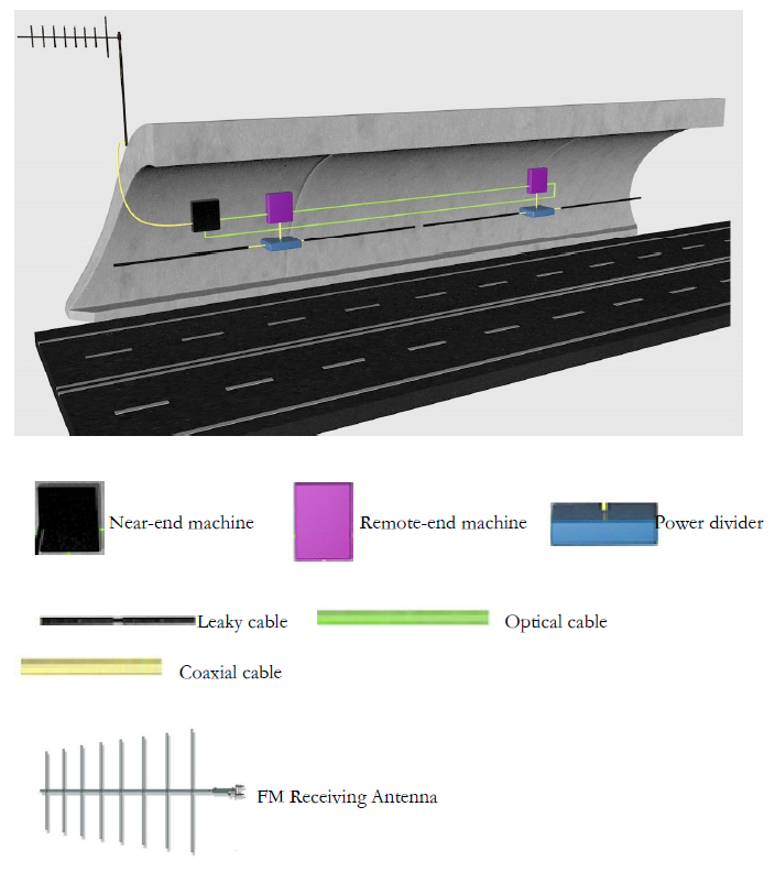
The system consists of outdoor full-band FM receiving antenna, near-end machine, optical cable, remote-end machine, leaky cable, emergency broadcast processing unit, remote monitoring unit, and other functional modules.

Figure 1. Diagram of tunnel equipment
2. Brief description of working principle:
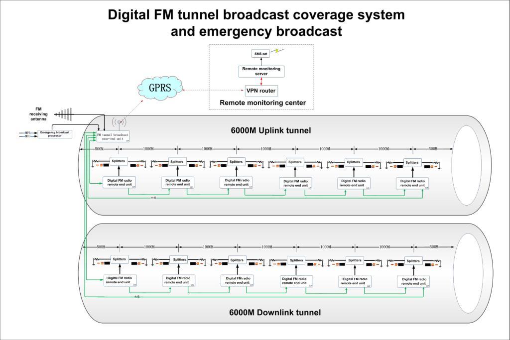
See "Figure 2. Digital FM tunnel broadcasting and emergency broadcasting system topology diagram".
The near-end machine is mainly composed of FM antenna pre-amplifier unit, FM broadcast signal digital processing unit, electro-optical conversion unit and optical signal transmission unit, emergency broadcast processing unit, remote monitoring unit, etc.
The remote-end machine is mainly composed of six parts: photoelectric module, band pass filter, power amplifier, low pass filter, power supply, and central control module MCU.
The outdoor FM full-band receiving antenna sends the received multi-channel FM broadcast signal to the near-end unit through a coaxial cable. The built-in high-gain antenna amplifier of the near-end unit amplifies the received FM signal, and the output RF signal passes through the band-pass filter. Perform digital processing (up to 16 channels can be selected for processing), after processing, convert electrical signals into optical signals and connect to optical ports to output optical signals
The near-end machine is equipped with four optical interfaces, which are divided into two groups for the transmission of optical signals in the uplink and downlink tunnels. The near-end machine is connected in series with each remote machine in the upstream and downstream tunnels through optical cables, and the remote machine at the end realizes loop networking through the connection of the optical cable and the near-end machine.
The remote monitoring system is implemented by the monitoring center through the 4G wireless link. In the monitoring center, the monitoring server and VPN router monitor the working status of the near-end and remote computers in real time through the 4G wireless link, and generate abnormal alarms.
The emergency broadcast system consists of an integrated emergency broadcast processor to complete the modulation and control functions. The processor can be inserted into a microphone for real-time broadcasting, or it can be inserted into a pre-recorded U disk for automatic playback; it can also receive audio signals from equipment such as mixers.
When emergency broadcasting is needed, only need to turn on the power of the processor to automatically carry out emergency broadcasting. At this time, the same emergency broadcast signal is broadcast at the preset 16 frequency points. When the processor power is turned off, the system will return to the normal broadcast state.
3. Features of digital FM tunnel broadcast coverage system
☆The near-end machine is equipped with 4 two-way digital optical modules, which can be flexibly combined with the remote machine according to the actual situation on site.This kind of network structure can not only ensure the low cost of the system, but also ensure the safe and reliable operation of the system.
☆The remote unit has an optical bypass function: when a remote unit in the network is powered off or components are damaged, the subsequent remote unit is not affected and can work normally.
☆When a fiber optic cable breaks in the ring network, the system can automatically adjust the link for self-healing to ensure that the remote devices continue to operate normally; at the same time, the monitoring software will report to locate the faulty fiber optic cable to facilitate timely maintenance.
☆Through the two-way optical network, the near-end machine performs real-time data communication with all the remote machines in the system, so as to realize the remote monitoring and monitoring of each remote machine.
☆The 4G wireless link is used as the remote monitoring channel, which greatly simplifies the configuration of monitoring equipment.
5G technology has laid a good foundation.
☆The emergency broadcast signal can be inserted at any time, so that all frequencies can broadcast emergency broadcast information. The car radio can listen to the emergency broadcast signal regardless of which frequency is listening.
☆The near-end machine adopts software radio technology and digital optical communication technology, integrating LNA, digital frequency selection, output level equalization, digital optical communication, emergency broadcast switching, remote monitoring and other functions in one. It is compact and extremely safe. high.
☆The remote machine adopts software radio technology, digital optical communication technology, and broadband linear amplification technology to achieve super-linear and AGC amplification of 16-channel FM broadcast signals, and remotely adjust power according to actual coverage needs.
☆The remote machine adopts a fully sealed, fanless design, and all parts are treated with "three preventions" to ensure long-term stable operation of the equipment.
4. Digital FM tunnel broadcast coverage system
1. Achieve high-quality coverage of 16 sets of FM stereo broadcast programs in a 6-km two-way tunnel. The field strength of the FM broadcast signal in the tunnel is not less than 35dBuV/m, which can meet the normal reception of the car FM radio.
2. The implementation method adopts leaky cable coverage (see Figure 3)
☆When a leaky cable is used as the radiating element, one remote machine is equipped every 1000 meters. A total of 1 near-end device and 10 25W remote units are equipped for both directions.
☆In order to ensure the uniform field strength of the broadcast signal in the tunnel, when the leaky cable is adopted, the RF output signal of the remote unit is sent to two 500-meter leaky cables on both sides after passing through the power splitter. (See Figure 3)
☆Networking in the form of optical loop to ensure that the system can still work normally after the optical cable breaks somewhere.
☆All near-end machines, remote machines, optical cables, leaky cables, etc. are wall-mounted, without a separate computer room.
☆The emergency broadcast signal can be inserted at the near-end unit after passing the emergency broadcast processor.
☆The near-end machine communicates with the control center through the 4G network to realize remote monitoring of itself and all remote machines.
☆Networking in the form of optical loop to ensure that the system can still work normally after the optical cable breaks somewhere.
☆All near-end units, remote units, optical cables, antennas, etc. are wall-mounted, without a separate room.
☆The emergency broadcast signal can be interrupted at the near-end unit after passing the emergency interrupt processor.
☆The near-end machine communicates with the control center through the 4G network to realize remote monitoring of itself and all remote machines.
Figure 2 . 6000M two-way tunnel FM broadcasting system equipment distribution map


